- 0755-21675210
- acdrive@micno.com.cn

2024-07-17
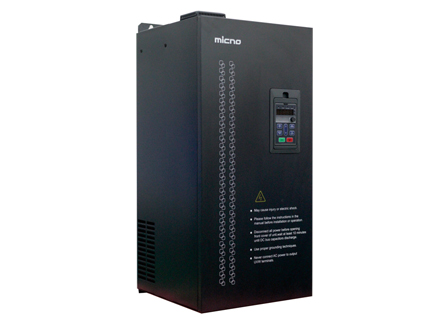
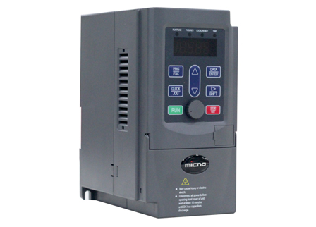
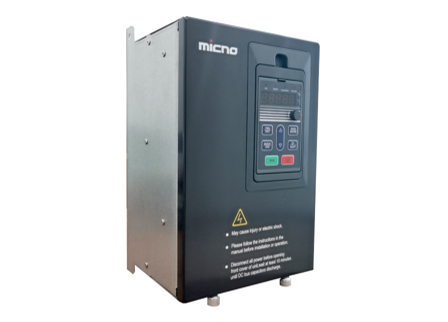
The frequency converter working principle is a complex but efficient process. Its core lies in converting the mains power (usually 50Hz or 60Hz) into AC power of various frequencies to achieve variable speed operation of the motor.
Rectifier: Converts the input AC power into DC power, providing a stable DC supply for subsequent stages.
Intermediate circuit: Smooths and filters the rectified DC power, reducing voltage and current fluctuations to provide a stable DC supply for the inverter.
Inverter: Converts the DC power back into AC power, with adjustable frequency and voltage to meet the demands of different motor speeds.
Control circuit: Receives feedback signals from the motor and the grid, periodically controls the switching devices of the inverter to adjust the output voltage and frequency, and has protective functions to ensure the safe and stable operation of the frequency converter.
These components work together to realize the core functionality of the frequency converter working principle.
The most important aspect of the frequency converter working principle is converting the input mains power into an adjustable frequency AC power through a series of circuits and control methods. This process mainly includes rectification, filtering, inversion, and control, which achieves the conversion from AC to DC and then back to AC (AC-DC-AC).
The frequency converter working principle involves four key processes: rectification, filtering, inversion, and control, together forming an efficient and flexible speed control device.
Rectification process: The AC power from the grid is converted into DC power through the rectifier circuit. This is the first step in the operation of the frequency converter, providing the necessary DC supply for subsequent stages.
Filtering process: The DC intermediate circuit smooths and filters the output of the rectifier circuit, making the DC voltage more stable and smoother. This process helps reduce voltage ripple and improve the efficiency of the inverter circuit.
Inversion process: Under the action of the control circuit, the inverter circuit "inverts" the DC power back into adjustable frequency AC power. The output voltage and frequency of the inverter circuit can be adjusted within a certain range to meet the speed control requirements of different motors.
Control process: The control circuit receives feedback signals from the motor and the grid, periodically controls the conduction of the inverter circuit to adjust the output voltage and frequency. Additionally, the control circuit is responsible for necessary protection and control operations to ensure the safe and stable operation of the frequency converter.
 English
  français
  Español
  русский
  português
  العربية
  tiếng việt
  ไทย
ไทย  中文
中文


 About MICNO
  Applications
 Construction Machinery

 Textile Machine
 Company News